This post explains a quick afternoon hack to turn a foot pedal controller for music synthesizers into a programmable USB foot keyboard.
A couple of weeks ago, for a personal project, my wife needed to manually transcribe many hours of interview recordings. Text-to-speech software were failing miserably both because of the people's strong local accent and poor recording quality. To ease the task she used the free version of Express Scribe, a nice dedicated application with a powerful transport bar that works exactly like 20th century tapes: rewind/forward while playing back, slow down/up playback speed, etc.
How cool would it be to control this with the feet, so that she could have her hands free for typing? At least his was the dubious excuse I needed for a hack I had been thinking about for quite some time :-)
The hardware
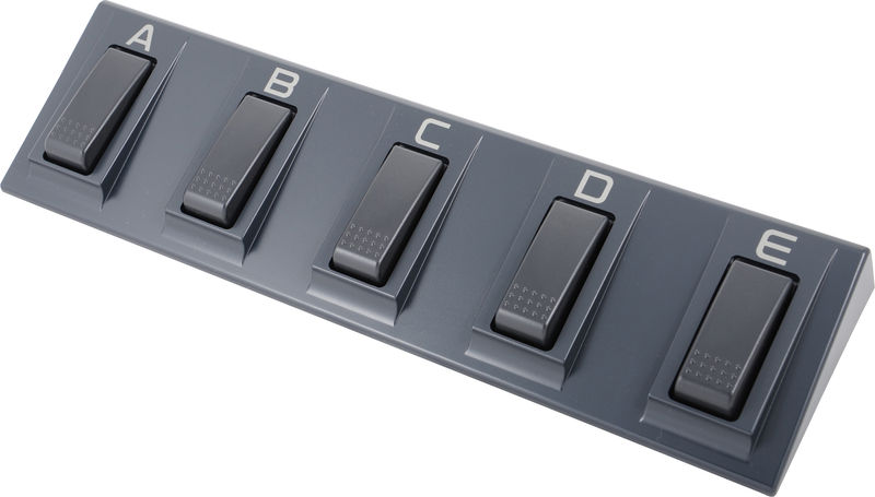
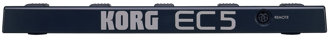
The Korg EC5 is a sturdy 5 pedals foot controller aimed at Korg's synthesizers. It's a dedicated device that has no MIDI nor USB interface. Its 6 pin connector is just wires to the 5 pedal switches and a common ground. We'll turn it into a programmable 5 keys USB "keyboard". Here's the pin layout of the EC5 output connector:

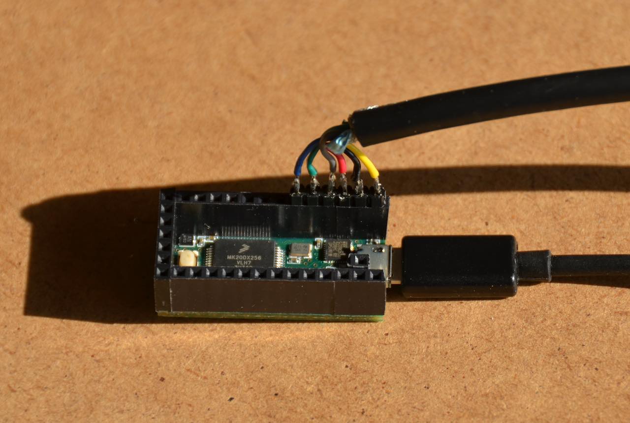
I am a big fan of Teensy microcontrollers (which I buy from my friends at Snootlab): this cheap tiny thing has a lot of inputs and outputs and can emulate almost any USB device: mouse, joystick, keyboard, MIDI devices, and even flight simulator controls! We just need to cut the EC5 cable and solder the wires on the Teensy's ground and digital inputs 0 to 4. That's all there is for the hardware part!
The code
The software to turn pedal switches into USB key presses is simple, but requires to understand basic concepts of digital I/O. Discussing with my colleagues, I realized that most developers have learned digital electronic basics during their studies, but often quickly forgot about it. This is what actually motivated me to write this post.
Here's the source code. As for all programs written with the Arduino
IDE, it's a single C++ file that instead of a standard main() has two
methods: setup() to initialize the system, and loop() that is called
over and over and where we read sensors, activate outputs, send data,
etc.
/*
 * Korg EC5 mapping to control Express Scribe
 * You must select "Keyboard" from the "Tools > USB Type" menu in the Arduino IDE
 */

#include <Bounce.h>

// Create a Bounce object for each pedal. The Bounce object
// automatically deals with contact chatter or "bounce", and
// makes detecting changes very simple.
Bounce pedalA = Bounce(0, 10);
Bounce pedalB = Bounce(1, 10);
Bounce pedalC = Bounce(2, 10);
Bounce pedalD = Bounce(3, 10);
Bounce pedalE = Bounce(4, 10);
We start by creating 5 debouncers, one for each key, with a 10 milliseconds delay. Debouncing is mandatory in the hardware world: when a switch changes state, the measured value can be randomly 0 or 1 for a brief period of time, until the contact is stabilized. This debouncer is a great example of the amazing Arduino ecosystem, that provides a lot of components with a simple API, even if under the hood the implementation may be really tricky.
byte playMode = false;
void setup() {
  // Configure the pins for input mode with pullup resistors.
  pinMode(0, INPUT_PULLUP);
  pinMode(1, INPUT_PULLUP);
  pinMode(2, INPUT_PULLUP);
  pinMode(3, INPUT_PULLUP);
  pinMode(4, INPUT_PULLUP);
}
The calls to pinMode() configure the pins as digital inputs and activate the internal pull-up resistor. What is this, and why is it needed?
When a switch is closed, its pin is connected the ground, and we measure
LOW (0 Volt). If the switch is open, its pin is "floating" and the
measure is unpredictable. To have a stable value when the switch is
open, we connect its output to Vcc (3.3 V for the Teensy) using a
resistor. This has the effect of "pulling up" the voltage of the pin to
a stable value that can be measured. The call to
digitalRead() will
then return HIGH if the measured voltage is higher than 2 Volt. Note
that we cannot simply connect the input pin to Vcc, as it would create a
short circuit when the switch is closed!
This value of 2 Volt comes from the fact that the pull-up resistor is combined with impedance of the microcontroller's analog to digital converter, which effectively creates a voltage divider.
The figure below outlines this:

If you want the nitty gritty details about calculating the value of pull-up resistors, read this Sparkfun tutorial or this reference documentation from Texas Instruments.
This pull-up resistor pattern is so common that microcontrollers now
have embedded pull-up resistors that can be activated via software. This
is what INPUT_PULLUP does: configure the pin as input, and activate
the internal pull-up resistor so that we have a stable and measurable
voltage when the switch is open, without requiring an external resistor.
This makes less parts and also avoids mistakes while prototyping.
void loop() {
  // Let pedal switches debouncers update their state.
  pedalA.update();
  pedalB.update();
  pedalC.update();
  pedalD.update();
  pedalE.update();
This the beginning of the loop that will continuously track the change in pedal switches states and send USB key presses whenever changes happen.
  // Debouncers track "falling" and "rising" edges on the signal,
  // that are triggered by pedal press and release.
  if (pedalA.fallingEdge()) Keyboard.press(KEY_F3);
  if (pedalA.risingEdge()) Keyboard.release(KEY_F3);
  if (pedalB.fallingEdge()) Keyboard.press(KEY_F4);
  if (pedalB.risingEdge()) Keyboard.release(KEY_F4);

  if (pedalC.fallingEdge()) {
    // Flip play mode
    playMode = !playMode;
    Keyboard.press(playMode ? KEY_F5 : KEY_F6);
  }
  if (pedalC.risingEdge()) Keyboard.release(playMode ? KEY_F5 : KEY_F6);

  if (pedalD.fallingEdge()) Keyboard.press(KEY_F7);
  if (pedalD.risingEdge()) Keyboard.release(KEY_F7);
  if (pedalE.fallingEdge()) Keyboard.press(KEY_F8);
  if (pedalE.risingEdge()) Keyboard.release(KEY_F8);
}
Express Scribe allows defining keyboard shortcuts for its actions. The default configuration doesn't include mappings for everything we want to control with the feet, so we've configured it as follows:
- F3 : reduce playback speed, mapped to pedal A
- F4 : rewind, mapped to pedal B
- F5 : play, mapped to pedal C
- F6 : pause, mapped to pedal C
- F7 : fast forward, mapped to pedal D
- F8 : increase playback speed, mapped to pedal E
All pedal switches except pedal C have the same behavior: when the pedal is pressed (falling edge of the measured value) we send a key press event. Conversely when there the pedal is released (rising edge) we send a key release event.
Pedal C (the middle pedal) is a single command for both play and pause, which is much more comfortable than having to move the foot to play and pause. This is why pressing pedal C send either F5 or F6 depending on the value of "playMode" which is flipped at each press of this pedal.
Conclusion
Writing this article took a lot more time than actually doing this little hack! But I hope to have demystified the basics of digital input with microcontrollers. If you know how to program, you just need some basic soldering skills to start hacking. And this also is easy to learn.
Now how about the usefulness of this for my wife? Well... it turned out that coordinating feet and hand movement isn't something you master instantly, and in the end she ended up using mostly the function keys on the Mac's keyboard...
Oh well, that was a fun experiment nonetheless and I now have a new toy to control programs in unusual ways. I have some sort of track record here, having used a Wii remote to draw virtual grafittis on a wall, a Kinect to draw 3D virtual wireframes with an augmented reality headset, and other weird things!